
Beginning the Project
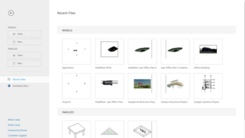
Open a new project. Once Revit is opened up it will show a screen of past projects and assorted options for opening up files. To create a new project, click on New… under Models on the left-hand side of the page. Once New… is selected a pop-up window will appear, showing various template options. Since this is a simple construction layout everything is already set to the correct settings, so simply select Okay without making any changes.

Familiarize yourself with the software. Once the new project fully loads, take time to notice all the various tools within the software. The properties tab on the left-hand side is where you will be able to customize varied materials. The project browser just below allows you to select elevations and floor plans to do different tasks in creating your building. The tabs along the top of the screen organize the tools used in creating the model. They categorize it to help keep the model organized and easy to use.
Building the Model
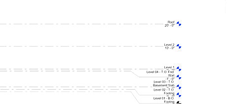
Create the elevations. Scroll down in the project browser on the left, to find the section for elevations. Double click the East elevation to show a screen as pictured above. Keep the elevation heights as listed. Level 1 is at 0’-0” which denotes ground level. Level 2 is 10’ from level 1. Similarly, the Roof is 20’ from level 1 and 10’ from level 2. This is set so that the wall heights are 10’. Though we are not changing the wall heights, for reference, if you were to have different wall heights double click on the numbers and type what height you prefer. The software will automatically adjust the lines to reflect the heights you choose.
[Wall Instructional Video] Lay out the walls. Begin at any point within the white area under the Level 1 floor plan as selected on the left-hand side. Click on the Architecture tab and then Walls. It will already be set to the type of wall necessary for this project, so you can click anywhere on the screen to begin creating the walls. From there you will put in the wall dimensions as shown in the video above. To put in the wall dimensions, click and then drag the wall in the desired direction, type in the length (It is expressed in feet), then click Enter. Continue this process following the dimensions in the video until you have the final layout of all the walls. If you make a mistake, click the Escape button on your keyboard to get out of the wall tool. Select Modify in the top left corner, select the wall you wish to delete, and select Delete on your keyboard. Additionally, make sure that the pink box in place of your curser shows when you are extending a new wall off of the end of an already created wall. The pink box makes sure that you are starting the new wall directly at the end of the existing one. If the new wall is not starting at the end of the existing wall, the system will not connect the walls correctly.
[Floor Instructional Video] Insert the floor. To insert the floor, select Floor in the Architecture tab. Select all four of the outside walls, but make sure the pink lines are along the inside of the walls. You want to make sure the pink lines are along the inside of the walls because that is where the floor will meet up with the walls in the model. If they are not along the inside of the outermost walls, click the symbol of two arrows going in opposite directions that appear in the middle of the line. This flips the line to the other side of the wall. Once all four lines are correct, click the green check at the top of the screen to complete your floor.
[Door Instructional Video] Place the doors. On the left-hand side, the Properties section shows what type of door is selected. Click on the drop-down arrow to select the door. The first door you will select is a Single Flush 32”x84”. Once that door type is selected you can place them in a similar place as shown in the video. Do not worry if it is in the correct place yet because you will correct it. The instruction video shows different doors being placed, however the basic Revit program only has the single flush doors, so use them in place of the others. Select the Single Flush 32”84” again and place it in the center of the closet wall. Notice that depending on where your mouse is, it moves what side the door opens on. Make sure that the doors open in the correct direction. Select the Single Flush 32”84” one more time and place it to where the outside entrance would be. Once all of the doors are placed zoom in to the location of the first door and select the door. When selected, dimensions show up. By pressing the blue dots it changes where the dimensions are measuring from. Click the blue dots so that we can specify 6” between the end of the door and the wall on all of the single flush doors. If any of the doors are opening on the wrong side, click the double arrows to ensure the door opens to the side shown in the video. There are also double arrows to flip what room the door opens into.
[Window Instructional Video] Place the windows. Begin by selecting the Window tool in the Architecture tab. Using the drop-down arrow select the window Double-hung 30”x46”. Place the windows in the same locations as the video, by dragging the window along the wall until it matches the correct dimensions. Make sure that the dark line of the window is on the outside of the building because that marks the outside of the window.
[Roof Instructional Video] Add a roof. Select the Roof tool in the Architecture tab. Make sure that the top left box that states “define slope” is checked, and there is a 2’ overhang. Ensure that the base level is selected to be Level 2. If the base level is not at level 2, then the roof will not sit on top of your walls correctly. Click Apply before beginning your roof. Select all four outer walls and click the green check mark to complete the roof. You will not be able to visibly see the roof just yet, but it is there.
Using Additional Tools.
[3D Instructional Video] Navigate 3D view. 3D view is a particularly valuable tool to create a different, more realistic perspective on your model. To use this tool, click the small house icon in the very top left corner. To alter the view, select or drag a side of the box in the top right of the project screen
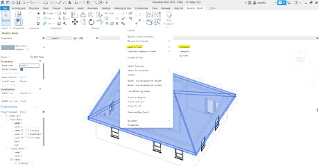
Hide elements. To take the next step you need to hide the roof from view. In 3D view, select the roof and right click. Select Hide in View, Elements, and then the roof will go away. If needed to bring the roof back, click on the light bulb icon along the bottom of the screen. From there select the roof, right click, and specify to Unhide in View. However, for the next step, keep the roof hidden from view.
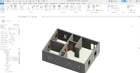
Make it look even more realistic. To make your model more detailed and realistic select the two icons (highlighted in the picture). Make sure they are specified to be Fine and Realistic. This makes it so that your model is more life-like and easy to picture.
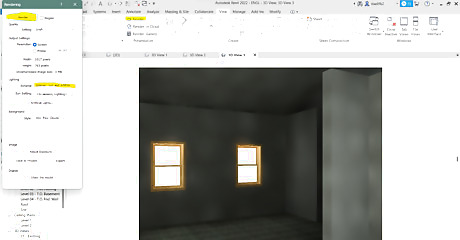
Create a rendering. Renderings are colorful and realistic ways to show the look and material of a building from a certain point of view. Click on the View tab, and the drop-down arrow below the house icon for 3D viewing. Click on Camera and click inside the top right corner of your building. Drag the view lines across the building to the opposite wall and click to confirm. Select the View tab, click Render, and a pop-up will appear. Specify the scheme to be Interior: Sun and Artificial. To create the rendering, click Render on the top of that pop up. Now you have a realistic camera view of your house!
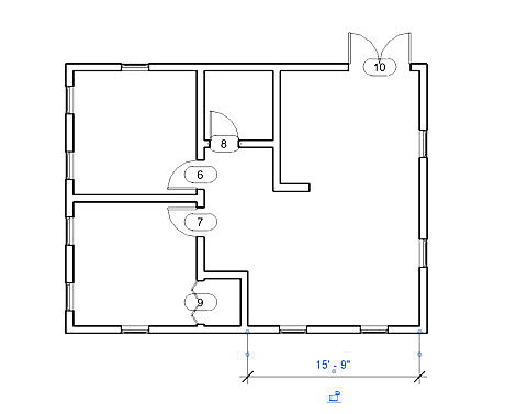
Add dimensions. For reference, if you use this tutorial to create your own layout of a building, it may be helpful to quickly find dimensions. Click on the Annotate tab and select Aligned. Click on the outermost right wall and the middle wall as shown in the picture, then drag it away from the building so that the number is visible and click to confirm. Select the blue dots to specify the inner sides of the walls, and make sure that it matches the number shown in the picture. This shows that the inner wall to inner wall is 15’-9”. You can use this tool to specify any dimensions that you need to know quickly.
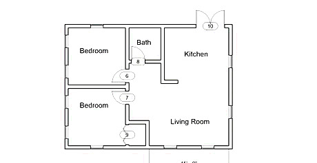
Add labels. Labels are used for reference and to organize your building layout. Select the Annotate tab and Text located in the middle of the banner. Specify 1/8” in the properties tab so that the labels fit within the rooms. Click in the middle of each room and label them as pictured above. Once they are all placed you have completed your building layout!


Comments
0 comment