views
Getting the Necessary Parts
Know where to look. You can find most of the electrical parts listed in this section in most stores which sell electrical or automotive supplies; additionally, you can find all of the parts listed here online at places such as Amazon and eBay. If possible, shop online for the components. You'll have a better opportunity to read reviews of the products, and you may qualify for a shipping discount.
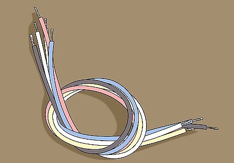
Purchase a pack of hook up wire. Hook up wire, also called circuit wire, is basic copper wire in a plastic sheath. If you have a choice, opt for stranded hook up wire rather than solid wire. Stranded is easier to manipulate and solder within the parameters of this project.
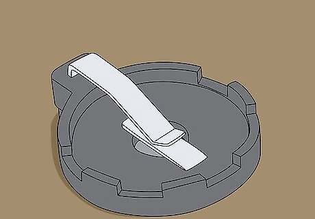
Buy a coin cell battery holder. This is essentially the body of your robot; it will hold the battery, host the main connections, and mount the "feet" of the robot. Make sure that your battery holder uses a clip to secure the battery. Your battery holder should have two basic wire connectors—one positive and one negative—on the bottom. If you find a holder which has a different layout, the assembly instructions may not work.
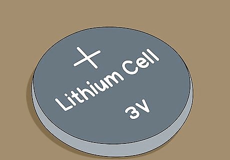
Purchase a 3V coin cell battery to fit your holder. Coin cell batteries are round, flat batteries which are often used to power items such as watches and other small electronics. You can find them in most department stores, though an electronics store or a Home Depot may be a better place to look.
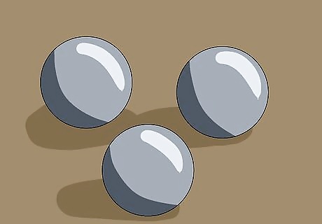
Find a few ball bearings. To create the robot's "feet", you'll need three 5/16ths inch diameter ball bearings. You can find these in several home appliances (e.g., old DVD players), but you can also purchase new ones at most automotive or electronics stores.
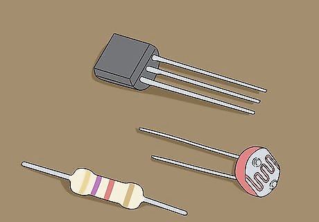
Buy the circuit components. In order to create the circuit that will tell the robot to move when exposed to light, you'll need the following items, all of which can be found online: One 4.7k resistor (1/2 W) One photoresistor (also called a photo cell) One 2N3904 transistor
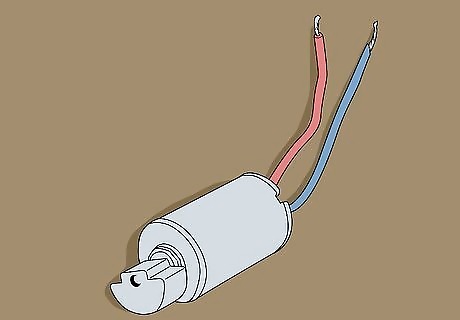
Find or buy a micro vibration motor. Vibration motors, such as the ones found in older cell phones, can be purchased online and in most electronics stores. Make sure you buy a model of vibration motor that has a red wire and a blue wire for its connections. If you have an old flip phone or pager, you can take it apart and pry out the vibration motor. Using a vibration motor which doesn't have red and blue wires will result in the assembly instructions not working.
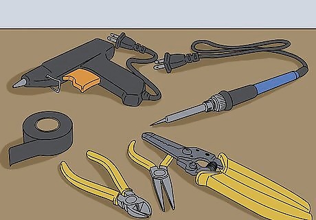
Make sure you have the correct tools. Before you can put together your robot, ensure that you have (and know how to use) each of the following items: Solder gun and solder Hot glue gun Wire cutters Wire strippers Needle nose pliers Electrical tape (or similarly opaque, easily removed tape)
Creating the Battery Compartment
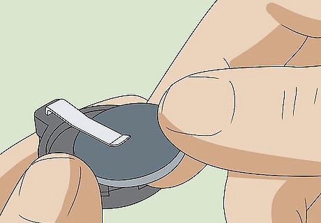
Make sure that your battery fits in the holder. Before you connect any wires to the battery holder, try sliding the battery into its slot and securing it with the built-in clamp. If the battery is too small or too large, you'll need to purchase the correct size before you can run your robot. Your battery holder's packaging or included documentation should have a section regarding the supported sizes of battery.
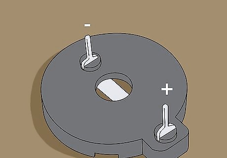
Find the battery holder's positive and negative connectors. These should be two pins on opposite sides of the bottom of the battery holder; the pin connected to the clamp which holds the battery is the positive connector, while the adjacent pin is the negative connector. You'll need to know which connector is which when attaching the motor and circuit to the battery holder.
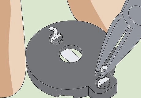
Use the needle nose pliers to bend down the connectors. The connectors should be bent away from the center of the battery holder so that they face outward.
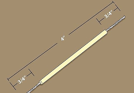
Prepare a hook up wire for soldering. Cut about four inches of hook up wire off of the spool, then use the wire strippers to remove 3/4 of an inch of tubing from each end of the wire.
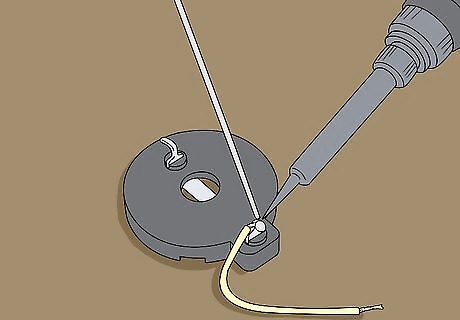
Solder the wire to the positive connector. Place an exposed end of the wire on the positive connector, then use your soldering gun and solder to cement the wire in place. Once you've successfully soldered the wire in place, you can proceed to the next part.
Creating the Circuit
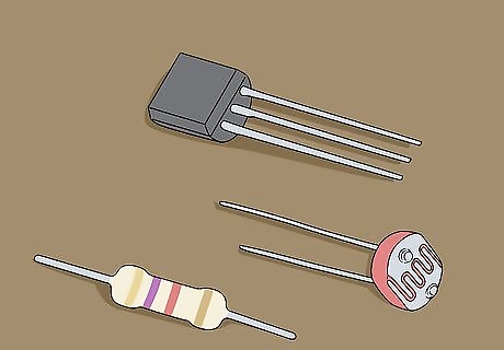
Lay out the resistor, photoresistor, and transistor. These are the components of your robot's circuit.
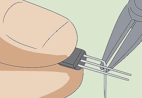
Bend away one of the transistor's three leads. While you'll use two of the transistor's wires (or "leads") in the circuit, one of the leads must be left alone for later; you can use the needle nose pliers to bend this lead over.
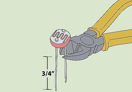
Trim the photoresistor's leads. The photoresistor's two leads are usually an inch to an inch and a half in length, so use the wire cutters to snip all but about 3/4 of an inch off of the leads. This will make the photoresistor less cumbersome to mount later.
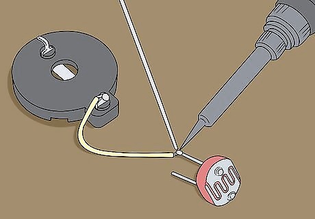
Connect the battery compartment to the photoresistor. Take the other exposed end of the wire that you soldered to the battery holder, then solder it to one of the photoresistor's leads.
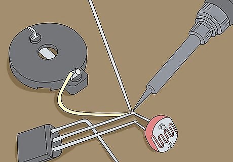
Connect the photoresistor to the transistor. Solder each of the photoresistor's leads to each of the unbent transistor leads.
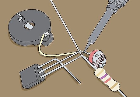
Connect the 4.7k resistor to the photoresistor. You'll solder one end of the resistor to the photoresistor lead that isn't connected to the battery compartment's wire. At this point, your photoresistor should have one lead that's connected to a transistor lead and the battery compartment wire, and one lead which is connected to a transistor lead and the resistor lead.
Building the Robot
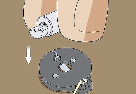
Attach the vibration motor. Place a couple of dots of hot glue on the bottom of the battery compartment, then quickly place the vibration motor on top of the hot glue and hold it there until it dries. You'll want to make sure the motor's weight isn't obstructed by any of the battery compartment's components. If you can't spin the motor's weight without the weight hitting something, re-glue the weight as needed.
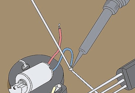
Connect the transistor to the vibration motor. Using the motor's blue wire and the remaining (bent) transistor lead, solder the two together.
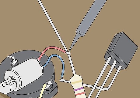
Connect the resistor and the motor to the negative connector. Solder both the resistor's free end and the motor's red wire to the negative connector on the bottom of the battery compartment. Remember, the negative connector is the one not attached to the first battery compartment wire you soldered.
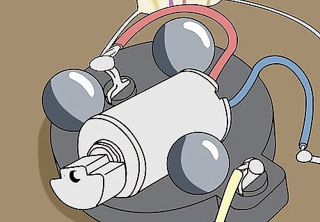
Glue the ball bearings to the bottom of the battery compartment. How you place these is up to you, but you'll most likely want to glue a ball bearing on both the left and right side of the motor and then fit the third one wherever you can.
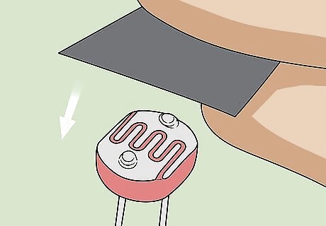
Cover the photoresistor's surface. Use a small piece of electrical tape to cover the flat portion of the photoresistor's head. This will prevent the robot from activating as soon as you place the battery.
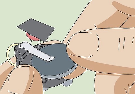
Place the battery in its slot. Lift the clamp on top of the battery compartment, then slide in the coin cell battery and release the clamp.
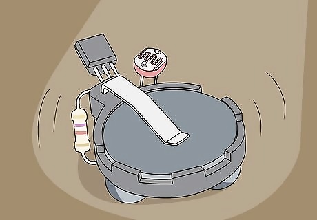
Turn on your robot. Place the robot on a flat, well-lit surface, then remove the piece of tape from the photoresistor. The robot should begin vibrating around the surface. Since the photoresistor is sensitive to light in general (not just sunlight), you'll want to cover the photoresistor when not using the robot.


Comments
0 comment