views
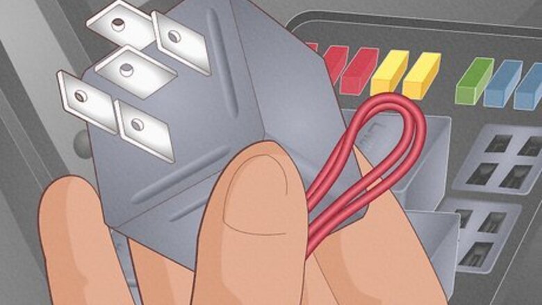
- Connect the relay’s 30 terminal to the vehicle battery’s positive terminal.
- Attach the relay’s 85 terminal to a nearby grounding spot on the vehicle’s engine or the battery’s negative terminal.
- Connect the 86 terminal to the switch that energizes the relay and operates the device or accessory you want to hook up.
- Attach the 87 terminal (and 87a terminal if there is one) to the device(s) you’re powering with the relay.
Wiring the Relay’s Terminals
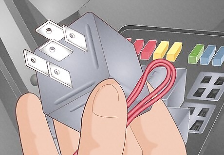
Use a relay and wires with the capacity for your vehicle and device. If you’re replacing a worn relay, this is simple—just use an identical relay to the one you’re ditching. Consult your vehicle’s service manual (not the owner’s manual) for specifications, or look at the outside of the relay. Most will have the voltage and amperage rating listed, and sometimes a usable part number to reference. If you’re unsure you have the right relay, confirm what type you need at a car dealership, auto shop, or with a mechanic. Confirm whether you need an SPST or SPDT relay and whether the large circuit needs to be normally open (NO) or normally closed (NC) when the relay is at rest. If you’re adding a new relay system, consult an automotive amperage chart to determine the gauge of wires needed, and make sure the relay can handle the amount of power needed for your new device or accessory.
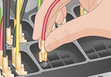
Connect the car battery’s positive terminal to the relay's 30 terminal. Turn off the ignition, then double check that the battery-end of the wire is secure. If you’re connecting a new wire, attach it with a ground wire connector or use a screwdriver to loosen the battery’s screw terminal (just loop the exposed wire around it, then tighten the screw to secure the wire). Then, attach the other end to the relay with a wire crimper and blade connector. Hold the exposed end of the wire against the blade connector, then slide both parts into the jaws of the wire crimper and press it closed to “fuse” the wire to the blade. Then, slide the blade connector onto the 30 terminal. The wire connecting the battery to the relay needs to run through a circuit breaker or fuse so the battery can’t overpower the relay and cause damage. Each terminal on the relay is numbered. The diagram on the side of the relay may not perfectly represent the terminal locations on the bottom, so look for numbers next to the actual terminals when in doubt.
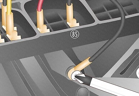
Attach a wire from the 85 terminal to a nearby grounding point. Choose a grounding point close to the relay to connect to. Use a spot on the engine for most accessory relays—the engine block, cylinder head, intake manifold (if it’s aluminum or cast iron), or the transmission-to-engine bolt—and attach the wire with a ground wire connector. Attach the other end of the wire to the 85 terminal with a wire crimper and blade connector. Use the battery’s negative terminal as a grounding point if the accessory you’re connecting isn’t sensitive to “background noise” (the other currents moving through the battery). This wire diverts power from the relay and into the metal frame of the car in case of a short circuit or other malfunction.
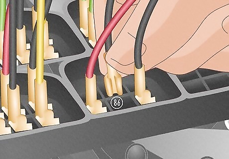
Connect the switch to the 86 terminal on the relay. This terminal brings low power from the switch into the relay to energize the coiled electromagnet inside. If you’re replacing an existing relay, a wire will already be connected to the switch. If you’re adding a new relay system, the way you connect the wire to the switch depends on how the switch is built (some may come pre-wired). In many cases, simply loop the exposed wire around a screw inside the switch, then tighten the screw to secure it. In relays where there is no safety resistor or diode present, the roles of terminals 85 and 86 are reversible.
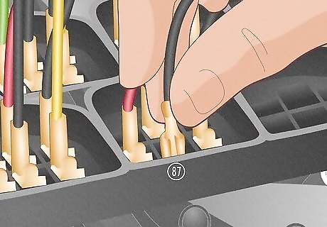
Attach the 87 terminal on the relay to the device or accessory it powers. The wire connecting these 2 points carries power from the relay into the device to turn it on. Connect the relay-end of the wire to the terminal with a blade connector and wire crimper, just like on the other terminals. The exact method for wiring the device depends on the device (you may need a plug-in connector, a screwdriver, or other tools based on what it is and how much power it needs). If you have an SPDT relay with a fifth terminal (87a), connect this to the appropriate device as well. Once all wires are securely fastened, the relay is ready for use. In some vehicles, there is a “ponytail” plug that gathers all 4 or 5 wires needed into one bundle. When these are present, just plug the relay into the bundle to connect all the wires.
Replacing an Existing Relay
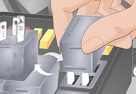
Unplug old relays from the fuse box and plug in identical new ones. In most cases, a vehicle’s relays are located near the fuse box under the hood. The terminals of manufacturer-installed relays often just “plug” into a bank of “outlets,” with all the wiring on the other side in bundles. To replace a relay, turn off the ignition and just pull the relay out with your fingers or pliers, then plug in the identical new one. Some relays that are installed this way may have a release tab. Push in the tab with your fingers while you pull the relay up and away. If you don’t spot the right relay under the hood, check underneath the dash.
Mounting a New Relay & Switch
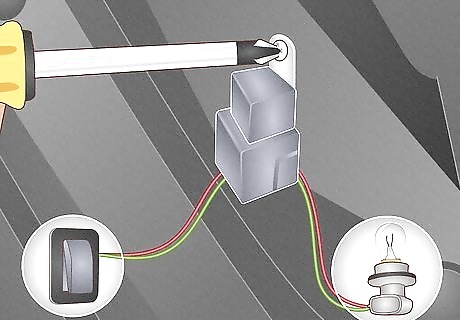
Mount a new relay between the switch and the device it powers. Find a location that minimizes the length of wires needed to connect your switch, relay, device, and car battery. If the wiring is external, attach a mounting bracket for automotive relays to a clear spot on the wall of the engine bay. If there’s no room or some of the wiring is internal, choose a spot underneath the dash on the driver’s side. Some vehicles have a spare spot in the fuse bank or relay box to add another relay. In that case, you don’t have to mount one to the engine bay.
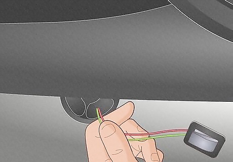
Feed wires from the switch to the relay through the vehicle’s firewall. Look underneath the dashboard on the driver’s side—you’ll see a rubber grommet in the firewall that leads to the engine compartment (there may be a removable cover over it). To feed wires through it, just poke a hole in the rubber with a screwdriver, then slide the ends of the necessary wires through it from the passenger compartment side. Use a long wire grabber to grab the ends of the wires once they’re through the firewall and pull them toward the relay. The wire connecting the switch to the relay will have to go through the firewall. The other wires that go through depend on whether the relay is inside or outside the engine compartment and where the device it’s powering is located. The firewall is what separates the engine compartment from the passenger compartment.
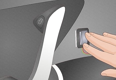
Attach the switch to the driver’s side door with double-sided adhesive. Check the instructions on your switch or relay kit and your car’s service manual for the best way to mount or place it. In many cases, it’s fine to just stick the switch onto the door with double-sided adhesive for easier access (and to shorten the length of wire needed to reach the relay).
How do relays work?
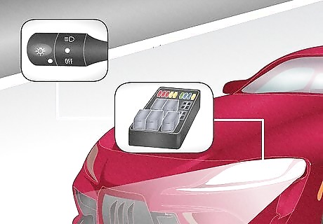
Relays use an electric signal from a switch to close a larger circuit. Imagine you’re hitting the “On” button for some offroading LED lights on top of your car. When you press the button, an electric signal travels to the relay and energizes an electromagnet inside (usually a copper wire coiled around a metal core). This generates an electromagnetic field that causes 2 metal contacts to move and touch each other, which completes a larger and more powerful electric circuit to power the lights. When you flip the lightswitch to “Off,” the electromagnet loses its charge and the metal contacts of the circuit move apart. This reopens the circuit and turns off the lights. With this relay system, a small electrical current of only 2-3 amps from the switch can activate a 50 amp (or more) circuit.
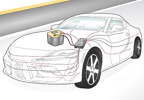
Relays save power and space in an automotive. Relays are found throughout your vehicle’s electrical system, controlling high-current flows from simple, low-current switches. This means thin wires are used to connect the switch to the relay, and heavy wires from the car’s battery (or other power source) only need to extend to the relay, not to the device it powers. This reduces the amount of heavy, space-hogging cables needed to power your car. Relay systems also allow power to travel the shortest distance from the power source to the device, which reduces voltage loss (the longer a wire is, the greater its resistance gets).
Common Relays in Automotives
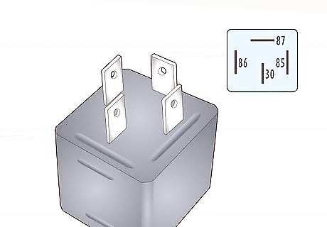
Single Pole Single Throw (SPST) relays with 4 terminals These relays are by far the most common relays found in cars, trucks, and other automotives. These relays resemble small cubicle or rectangular boxes with 4 terminals (also called pins or blades) sticking out of one side that connect to various wires. The 4 terminals are labeled 30, 85, 86, and 87 after DIN-standard relay terminal numbers (a German numbering system for automotive electrical terminals adopted by nearly all manufacturers since the 1980s). SPST relays are normally open, meaning the circuit stays disconnected unless the relay is activated by a switch. Terminal 30 channels high power from the vehicle’s battery into the relay. When the relay is activated, a circuit closes between terminals 30 and 87. Terminal 85 grounds the relay to the body of the vehicle. Grounding wires redirect electrical current to the frame of the car in case of short circuits. Terminal 86 brings low power into the relay from the switch. This terminal charges the relay’s electromagnet, which closes the circuit. Terminal 87 sends power out of the relay into the device it’s powering. When the relay is energized, current flows into terminal 30 and out of terminal 87.
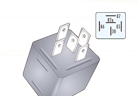
Single Pole Double Throw (SPDT) relays with 5 terminals Also called “changeover” relays, these resemble SPSTs, except they have a fifth terminal marked 87a. Terminals 87 and 87a each close a different circuit, but never at the same time. For example, terminal 87’s circuit will remain open (off) while terminal 87a’s circuit is closed (on). When the switch is flipped and the electromagnet is energized, the circuits flip—terminal 87 is now closed while 87a is open. The design of the relay determines whether terminal 87 or 87a is activated while the relay is energized. Terminal 87 is normally open. SPDTs are less common in vehicles than SPSTs. They’re useful for functions that can run in reverse, like electric windows that move both up and down or trunk door motors that open and close.
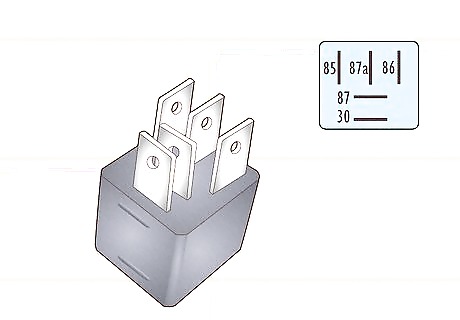
Mini and micro relays In most modern vehicles, you may see smaller relays that can handle the same amount of power as older, larger ones. Mini relays are usually 1 in (2.5 cm) cubes, while micro relays are about half that size (the layout of the terminals looks different, but they function the same). The terminals are labeled 1 through 5 and correspond to the DIN-standard numbers: 1 to 85, 2 to 86, 3 to 30, 4 to 87a, and 5 to 87. Relays of any kind may also have a built-in time delay. This means there is a delay between when you hit the switch and when the relay energizes (or de-energizes). The delay length is adjustable on some relays. Some relays also include a resistor or diode, which prevents high voltage currents from damaging sensitive electronics when the electromagnet is suddenly de-energized.


Comments
0 comment